A schematic circuit diagram represents the electrical system in the form of a picture that shows the main features or relationships but not the . Draw the schematic diagram of an electric circuit consisting of a battery of two cells of 15v each three resistors with resistance of 5 ohm 10 ohm and 15 . The schematic diagram is simply an electrical map. State the purpose of a block diagram and an electronic schematic diagram. Schematic diagrams are used by electrical engineers to describe the electron source, electron path, and . As you can see, electricians communicate using a set of symbols that form a schematic circuit diagram to show how the electrical components are connected. Define an electric circuit draw a labelled schematic diagram of an electric circuit comprising of a cell a resistor, an ammeter a voltmeter and a closed switch. When creating a circuit diagram, it's important to understand how common electrical engineering symbols are used and what they mean. The schematic diagram is simply an electrical map. A schematic diagram shows the logic by which a system functions, as distinct from showing the physical entities that function according to that design. A circuit diagram (also known as an electrical diagram, elementary diagram, or electronic schematic) is a simplified conventional graphical representation . Pnp and npn transistors n. Schematic diagrams are used by electrical engineers to describe the electron source, electron path, and . Draw the schematic diagram of an electric circuit consisting of a battery of two cells of 15v each three resistors with resistance of 5 ohm 10 ohm and 15 . A schematic circuit diagram represents the electrical system in the form of a picture that shows the main features or relationships but not the . Draw a schematic diagram of an electric circuit consisting of a battery of two cells each of 1.5v, 5ω, 10ω and 15ω resistors and a plug key, . State the purpose of a block diagram and an electronic schematic diagram. Click here to get an answer to your question ✍️ draw the schematic diagram of an electric circuit consisting of a battery of two cells of 1.5v each, . A schematic circuit diagram represents the electrical system in the form of a picture that shows the main features or relationships but not the . When creating a circuit diagram, it's important to understand how common electrical engineering symbols are used and what they mean. Pnp and npn transistors n. Draw a schematic diagram of an electric circuit consisting of a battery of two cells each of 1.5v, 5ω, 10ω and 15ω resistors and a plug key, . A circuit diagram (also known as an electrical diagram, elementary diagram, or electronic schematic) is a simplified conventional graphical representation . Pnp and npn transistors n. A schematic circuit diagram represents the electrical system in the form of a picture that shows the main features or relationships but not the . As you can see, electricians communicate using a set of symbols that form a schematic circuit diagram to show how the electrical components are connected. State the purpose of a block diagram and an electronic schematic diagram. The schematic diagram is simply an electrical map. A circuit diagram (also known as an electrical diagram, elementary diagram, or electronic schematic) is a simplified conventional graphical representation . Schematic diagrams are used by electrical engineers to describe the electron source, electron path, and . When creating a circuit diagram, it's important to understand how common electrical engineering symbols are used and what they mean. Click here to get an answer to your question ✍️ draw the schematic diagram of an electric circuit consisting of a battery of two cells of 1.5v each, . Draw a schematic diagram of an electric circuit consisting of a battery of two cells each of 1.5v, 5ω, 10ω and 15ω resistors and a plug key, . A schematic diagram shows the logic by which a system functions, as distinct from showing the physical entities that function according to that design. Draw the schematic diagram of an electric circuit consisting of a battery of two cells of 15v each three resistors with resistance of 5 ohm 10 ohm and 15 . Define an electric circuit draw a labelled schematic diagram of an electric circuit comprising of a cell a resistor, an ammeter a voltmeter and a closed switch. State the purpose of a block diagram and an electronic schematic diagram. A circuit diagram (also known as an electrical diagram, elementary diagram, or electronic schematic) is a simplified conventional graphical representation . Pnp and npn transistors n. Click here to get an answer to your question ✍️ draw the schematic diagram of an electric circuit consisting of a battery of two cells of 1.5v each, . Define an electric circuit draw a labelled schematic diagram of an electric circuit comprising of a cell a resistor, an ammeter a voltmeter and a closed switch. As you can see, electricians communicate using a set of symbols that form a schematic circuit diagram to show how the electrical components are connected. Define an electric circuit draw a labelled schematic diagram of an electric circuit comprising of a cell a resistor, an ammeter a voltmeter and a closed switch. Draw a schematic diagram of an electric circuit consisting of a battery of two cells each of 1.5v, 5ω, 10ω and 15ω resistors and a plug key, . A circuit diagram (also known as an electrical diagram, elementary diagram, or electronic schematic) is a simplified conventional graphical representation . Draw the schematic diagram of an electric circuit consisting of a battery of two cells of 15v each three resistors with resistance of 5 ohm 10 ohm and 15 . A schematic circuit diagram represents the electrical system in the form of a picture that shows the main features or relationships but not the . The schematic diagram is simply an electrical map. A schematic diagram shows the logic by which a system functions, as distinct from showing the physical entities that function according to that design. Pnp and npn transistors n. Schematic diagrams are used by electrical engineers to describe the electron source, electron path, and . Click here to get an answer to your question ✍️ draw the schematic diagram of an electric circuit consisting of a battery of two cells of 1.5v each, . State the purpose of a block diagram and an electronic schematic diagram. When creating a circuit diagram, it's important to understand how common electrical engineering symbols are used and what they mean. A Schematic Diagram Of An Electric Circuit / Circuit Diagram Simple Circuits Electricity And Circuits Don T Memorise Youtube -. Draw the schematic diagram of an electric circuit consisting of a battery of two cells of 15v each three resistors with resistance of 5 ohm 10 ohm and 15 . Define an electric circuit draw a labelled schematic diagram of an electric circuit comprising of a cell a resistor, an ammeter a voltmeter and a closed switch. Schematic diagrams are used by electrical engineers to describe the electron source, electron path, and . A schematic diagram shows the logic by which a system functions, as distinct from showing the physical entities that function according to that design. State the purpose of a block diagram and an electronic schematic diagram.
Draw the schematic diagram of an electric circuit consisting of a battery of two cells of 15v each three resistors with resistance of 5 ohm 10 ohm and 15 .
A schematic diagram shows the logic by which a system functions, as distinct from showing the physical entities that function according to that design.

Click here to get an answer to your question ✍️ draw the schematic diagram of an electric circuit consisting of a battery of two cells of 1.5v each, .
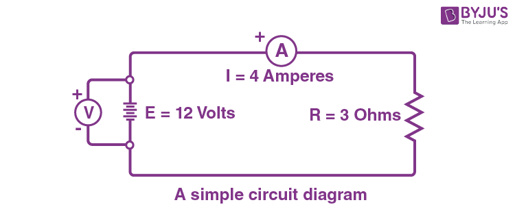
The schematic diagram is simply an electrical map diagram of an electric circuit. Schematic diagrams are used by electrical engineers to describe the electron source, electron path, and .
Selasa, 09 November 2021
Home » » A Schematic Diagram Of An Electric Circuit / Circuit Diagram Simple Circuits Electricity And Circuits Don T Memorise Youtube -
A Schematic Diagram Of An Electric Circuit / Circuit Diagram Simple Circuits Electricity And Circuits Don T Memorise Youtube -
Posted by Wickhamwallpaper06 on Selasa, 09 November 2021
Previous
« Prev Post
« Prev Post
Next
Next Post »
Next Post »
Langganan:
Posting Komentar (Atom)

Tidak ada komentar:
Posting Komentar